
MEP BIM Coordination for AI Data Centers: Power, Cooling & Fire Protection

Data centers bring together dense electrical distribution, cooling systems, plumbing, fire protection, structural elements, and equipment access requirements within limited technical spaces.
As computing density increases, these systems demand more routing space and closer coordination. A chilled-water line may compete with a cable tray, a busway may interfere with fire protection piping, or equipment may fit physically while leaving insufficient room for maintenance.
These are not isolated modeling problems. They are coordination problems.
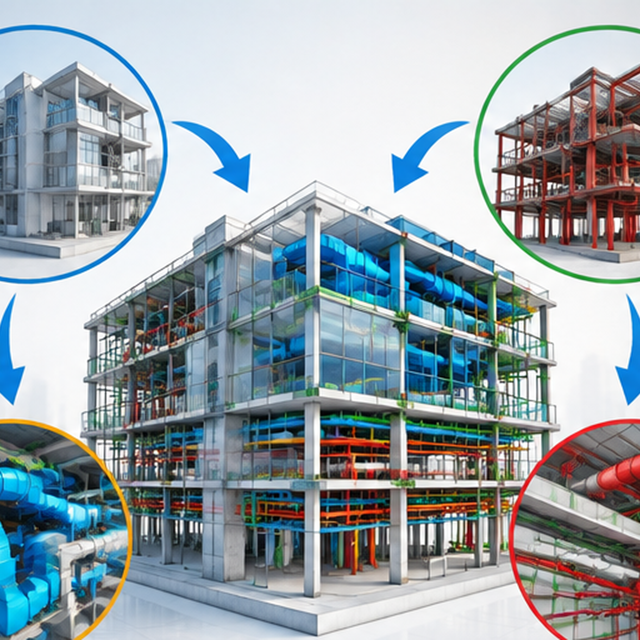
MEP BIM coordination brings mechanical, electrical, plumbing, fire protection, architectural, and structural information into a coordinated digital environment so that spatial conflicts, access issues, and constructability concerns can be identified before installation.
For data center projects, this helps project teams make routing and installation decisions with a clearer understanding of how all building systems interact.
Why MEP Coordination Is Critical for Data Centers
Building systems inside a data center cannot be coordinated independently.
Electrical infrastructure influences cooling requirements. Cooling pipes and equipment affect routing space. Fire protection shares many of the same overhead zones, while structural and architectural conditions determine where services can pass and where equipment can be accessed.
A change to one system can therefore affect several others.
This is why effective BIM coordination is about more than removing geometric clashes. The objective is to develop building systems that can be constructed, accessed, maintained, and documented without creating avoidable conflicts between project teams.
Coordinating Power Infrastructure
Electrical systems occupy a significant amount of space within data center environments.
Depending on project requirements, the electrical BIM model can include transformers, switchgear, UPS systems, generators, power distribution units, electrical panels, busways, cable trays, conduits, and related infrastructure.
The coordination challenge extends beyond equipment placement. Routing, working clearances, connections, and installation space must also be considered.
Cable Tray, Busway, and Conduit Routing
Cable trays, conduits, and busways frequently share space with cooling pipes, ductwork, fire protection services, structure, and other building systems.
Through electrical BIM coordination, these systems can be reviewed together before installation.
The coordination team can check elevations, offsets, crossings, equipment connections, and routing zones to determine whether the proposed arrangement is practical.
A cable tray may appear clear in plan view but conflict with another service at a different elevation. Similarly, a busway may avoid a hard clash while still affecting equipment access or installation space.
A coordinated 3D model makes these conditions easier to identify.
Electrical Equipment Clearances
Electrical equipment also requires working and maintenance space.
Switchgear, panels, UPS systems, and related equipment may be correctly located while another service passes through a required clearance zone.
Representing these clearances during coordination helps project teams review both equipment placement and future accessibility.
Coordinating Cooling Systems
Cooling infrastructure is another major source of congestion within data center projects.
The mechanical model may include chillers, pumps, cooling equipment, chilled-water piping, supply and return headers, valves, and associated services.
These systems often require large routes and significant maintenance space, making early coordination important.
Cooling Distribution
Large mechanical piping has to be coordinated with electrical distribution, fire protection, structure, and equipment areas.
The BIM coordination model helps teams review routing, elevations, risers, equipment connections, valve access, penetrations, and maintenance clearances in a common environment.
Resolving major cooling routes early can also reduce later changes to surrounding services.
Coordination Near Equipment Areas
As cooling services move closer to equipment areas, the available routing space becomes tighter.
Mechanical piping may need to share space with busways, cable trays, conduits, fire protection systems, and structural components.
This is where 3D BIM coordination services help project teams understand the actual spatial relationship between systems and determine whether proposed routes can be installed and maintained as intended.
Coordinating Fire Protection Systems
Fire protection systems must also be coordinated within spaces occupied by mechanical and electrical infrastructure.
Depending on project scope, the BIM model may include fire protection mains, branch piping, valves, associated equipment, and penetrations through walls or slabs.
Typical coordination issues include fire protection piping crossing cable trays, conflicting with ductwork or structure, or creating access problems around other services.
Coordinating fire protection alongside mechanical and electrical systems allows the project team to resolve these conditions before major routes are finalized.
How the BIM Coordination Process Works
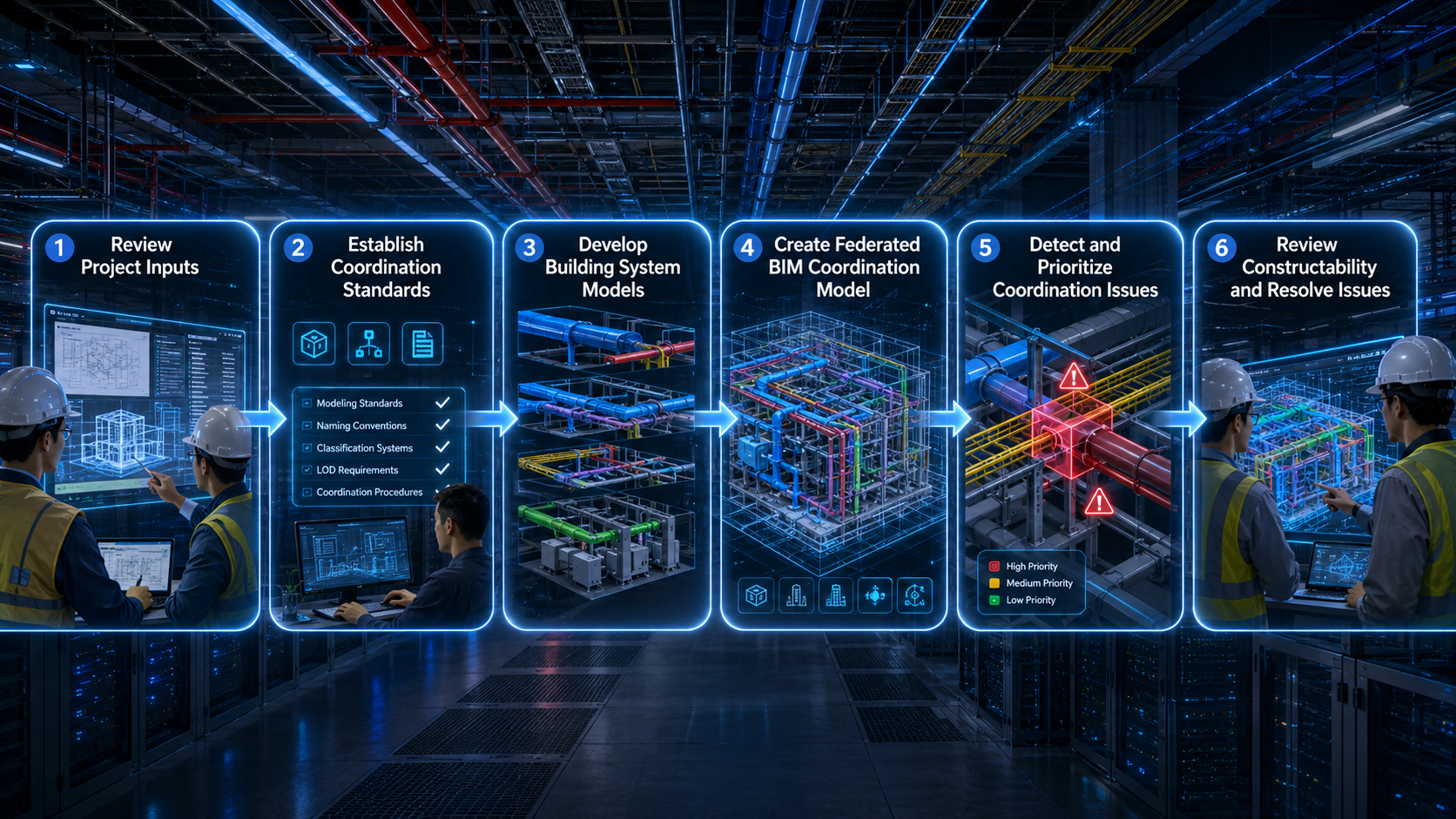
A structured BIM coordination process helps move the project from design information toward coordinated construction documentation.
1. Review Project Inputs
The coordination team begins by reviewing available architectural, structural, mechanical, electrical, plumbing, fire protection, equipment, and BIM information.
The goal is to understand what has been provided, identify missing information, and confirm project requirements before detailed modeling begins.
2. Establish Coordination Standards
Project requirements should define how the teams will work within the BIM environment.
This normally includes model coordinates, required Level of Development, file exchange procedures, update frequency, clash responsibilities, issue tracking, and approval workflows.
Clear standards reduce confusion and help all project teams coordinate against the same expectations.
3. Develop Building System Models
Each project team develops its model to the level required for coordination.
Construction-focused models may need to represent actual equipment dimensions, pipe and duct sizes, cable trays, conduits, fittings, connections, access zones, and required clearances.
The model detail should always match its intended use.
4. Create a Federated BIM Coordination Model
Mechanical, electrical, plumbing, fire protection, architectural, and structural models are brought together into a shared environment.
This federated BIM coordination model allows project teams to review building systems together for clash detection, clearances, constructability, routing, and installation planning.
5. Detect and Prioritize Coordination Issues
BIM coordination software can identify intersections between different systems, but the coordination team must determine which issues have a genuine impact on construction.
A conflict affecting a major pipe route, electrical clearance, equipment access, or structural opening usually requires more attention than a minor model intersection.
Clashes should therefore be reviewed, classified, assigned, and resolved according to their construction impact.
6. Review Constructability and Resolve Issues
The model should also be checked for conditions that may not appear as hard clashes, such as restricted access, difficult installation sequencing, or insufficient maintenance space.
Project teams then review unresolved issues, agree on practical solutions, update their models, and recheck the coordinated condition.
This cycle continues until the required coordination status is achieved.
Why Clash Detection Alone Is Not Enough
Clash detection identifies where model elements intersect. MEP BIM coordination goes further by determining whether the proposed arrangement is practical for construction and maintenance.
A pipe may technically avoid a cable tray but still leave inadequate room for installation, insulation, supports, or access.
This is why coordination requires technical judgement in addition to software-based clash detection.
The goal is not simply to produce a model with fewer clashes. It is to produce a coordinated arrangement that can support actual construction.
BIM Coordination Software Used in the Workflow
Different tools support model development, clash detection, coordination, and issue management.
Techture works with platforms including:
Autodesk Revit for detailed BIM modeling and construction documentation.
Navisworks Manage for model federation, clash detection, and coordination reviews.
Autodesk Construction Cloud for model sharing, coordination, and issue management.
Revizto for model-based issue tracking and collaboration.
Solibri for model checking and coordination reviews.
The software supports the workflow, but effective coordination still depends on model quality, clear responsibilities, technical review, and timely issue resolution.
Data Center Areas That Need Closer Coordination
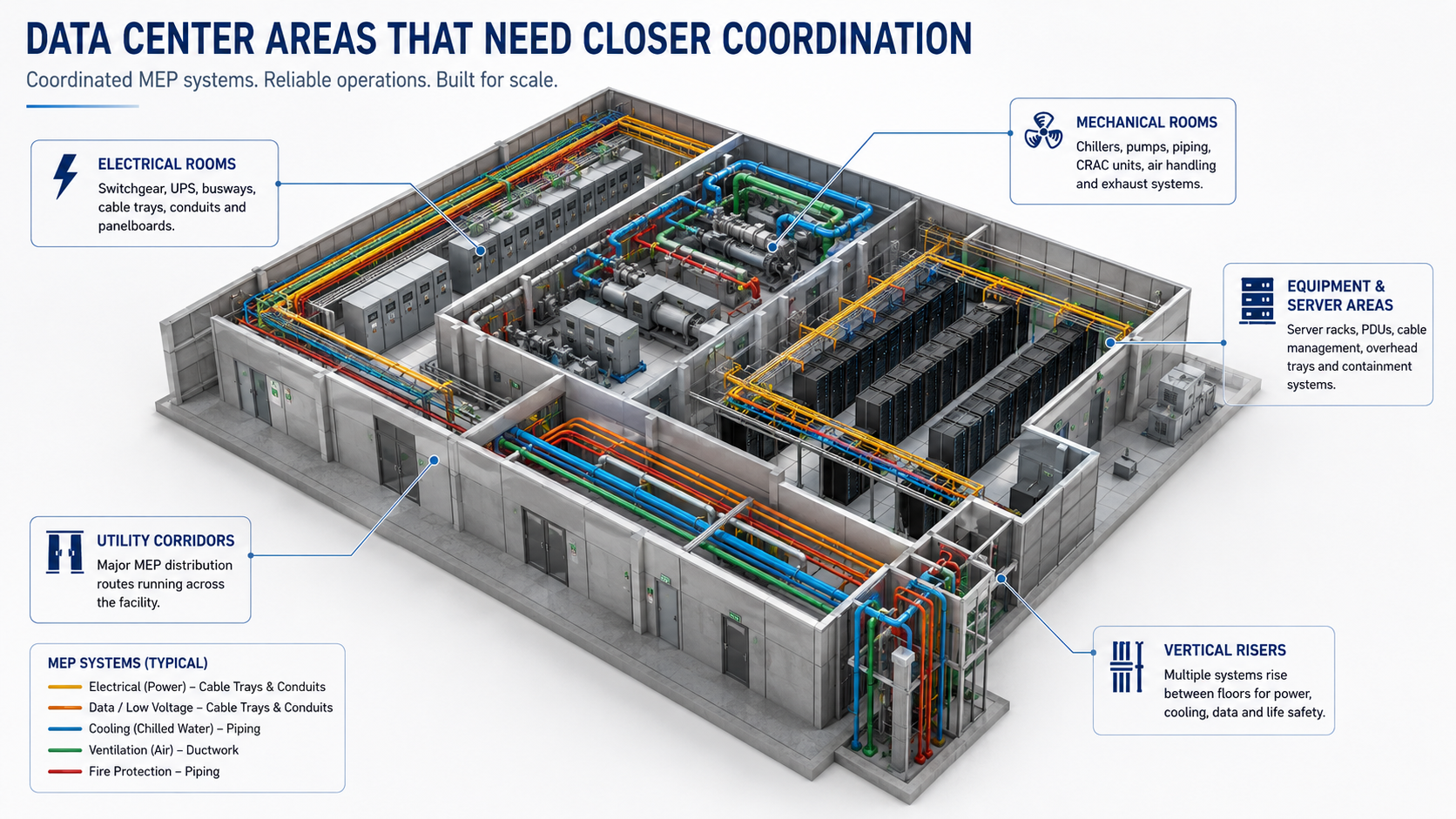
Certain project areas usually require more detailed review because multiple systems come together within limited space.
Electrical Rooms
Electrical rooms combine equipment, cable trays, conduits, busways, cooling services, and fire protection. Equipment clearances and maintenance access must be coordinated alongside routing.
Equipment and Server Areas
These spaces can contain dense electrical distribution, cooling infrastructure, fire protection, controls, and cable pathways. Routing needs to remain organized and accessible.
Mechanical Rooms
Large equipment, piping, valves, ductwork, and maintenance areas must be coordinated so equipment can be installed and serviced.
Utility Corridors and Risers
Major distribution routes often share limited horizontal and vertical space. Early coordination helps avoid overlapping systems and repeated rerouting.
BIM Coordination for Prefabrication
Prefabrication increases the importance of coordination accuracy because components manufactured away from the project site have less flexibility for field adjustment.
Coordinated BIM models can support shop drawings, pipe spool drawings, prefabricated assemblies, penetration layouts, and other construction information.
Before information is released for fabrication, dimensions, elevations, connection points, and surrounding clearances should be properly coordinated.
Typical MEP BIM Coordination Deliverables
Depending on project scope, MEP BIM coordination can support deliverables such as:
- Coordinated BIM models
- Clash detection reports
- Coordination drawings
- MEP and electrical shop drawings
- Equipment and penetration layouts
- Spool or prefabrication drawings
- As-built BIM models
These requirements should be established early so the models are developed with their final use in mind.
What Should Be Defined Before MEP BIM Coordination Begins?
Before coordination starts, project teams should establish the requirements that will guide model development, issue resolution, and final delivery.
Level of Development
The required LOD should match how the model will be used. A model intended for general coordination may require less detail than one supporting shop drawings or prefabrication.
Coordination Scope
The project team should confirm which project teams are included in the coordination scope, such as mechanical, electrical, plumbing, fire protection, architectural, and structural teams.
Trade Routing Priorities
Routing priorities should be established early so project teams can make consistent decisions when several systems compete for the same space.
Clash Classification
The team should define how coordination issues will be prioritized so major construction and access conflicts are addressed before minor model intersections.
Model Updates and Approvals
Model exchange frequency and approval responsibilities should be established to reduce coordination based on outdated information and avoid delays in resolving changes.
Final Deliverables
The team should confirm whether the project requires coordinated models, clash reports, shop drawings, penetration drawings, prefabrication information, or as-built BIM.
How Techture Supports MEP BIM Coordination
At Techture, MEP BIM coordination is approached as a construction-focused process rather than simply a model-checking activity.
The process begins with understanding project inputs, model requirements, coordination responsibilities, and expected deliverables.
Mechanical, electrical, plumbing, and fire protection systems can then be coordinated with architectural and structural information within a common model environment.
Depending on project scope, Techture's BIM coordination capabilities can support:
- MEP BIM modeling
- Electrical BIM coordination
- Mechanical and fire protection coordination
- Multi-trade model federation
- Clash detection and constructability reviews
- Coordination meetings and issue tracking
- Shop drawing and prefabrication support
- Construction documentation
- As-built BIM
The aim is to resolve coordination issues while they are still within the digital model rather than after installation has begun.
For complex data center projects, this gives project teams a clearer basis for coordinated routing, construction documentation, and installation planning.
Frequently Asked Questions
1. What is the difference between clash detection and MEP BIM coordination?
Clash detection identifies physical or spatial conflicts between model elements. MEP BIM coordination includes reviewing those conflicts, determining practical solutions, coordinating changes between project teams, and updating the models. Clash detection is therefore one part of the wider BIM coordination process.
2. What Level of Development is typically required for MEP BIM coordination?
The required LOD depends on the intended use of the model. Design coordination may require less detail, while construction coordination, shop drawings, or prefabrication can require more accurate equipment dimensions, routing, connections, and clearances.
3. Which project teams are typically involved in MEP BIM coordination?
The coordination process can involve mechanical, electrical, plumbing, fire protection, architectural, and structural teams. Including the relevant project teams helps identify both direct clashes and wider constructability or access issues.
4. What are the typical deliverables from MEP BIM coordination?
Typical deliverables can include coordinated BIM models, clash reports, coordination drawings, MEP shop drawings, electrical shop drawings, equipment layouts, penetration drawings, prefabrication information, and as-built BIM models depending on the project scope.
Final Thoughts
Data centers combine dense electrical infrastructure, cooling systems, fire protection, structural constraints, equipment clearances, and limited routing space.
These systems need to work together before they reach the field.
That is why MEP BIM coordination should be treated as a construction-planning process rather than only a clash-detection exercise.
A coordinated model gives project teams a clearer understanding of how systems interact, helps identify routing and access issues earlier, and supports more reliable construction documentation and installation planning.
The value of BIM coordination is not simply finding more clashes. It is resolving the issues that can affect construction while they are still easier to manage digitally.